How to Replace Rear CV Axle Half Shaft 2005-10 Chrysler 300
Created on: 2017-01-23
Our experts in this video will show all of the steps required to remove and replace the CV Axle yourself on the 05-10 Chrysler 300
-
step 1 :Removing the Wheel
- Loosen the lug nuts with the vehicle on the ground
- Raise the vehicle with a floor jack
- Secure the vehicle on jack stands
- Remove the lug nuts
- Pull off the wheel
-
step 2 :Removing the Axle Nut
- Thread a lug nut onto a spline
- Insert a 22mm wrench onto a spline
- Thread a lug nut over the wrench
- Lower the vehicle to the ground
- Remove the axle nut
- Raise the vehicle
- Insert a flat punch into the divet in the center of the axle
- Hammer the punch to tap the splines free
-
step 3 :Removing the Brake Pads
- Remove the two 13mm bolts from the caliper bracket
- Pull the caliper off
- Put the caliper aside
- Pry the brake pads off with a flat blade screwdriver
-
step 4 :Removing the Brake Rotor
- Remove the two 18mm bolts from the caliper bracket
- Pull off the brake caliper bracket
- Strike the drum surface of the rotor with a hammer to loosen the rotor
- Pull the rotor off
- Clean the hub surface with a wire brush
-
step 5 :Removing the Hub Assembly
- Remove the four E12 inverted Torx bolts from the back of the spindle
- Remove the wheel hub and bearing
-
step 6 :Removing the CV Axle
- Remove the 18mm bolt securing the upper control arm to the spindle
- Remove the 18mm nut on the control arm from the bolt going through the hub
- Remove the 18mm control arm bolt at the rear of the spindle
- Remove the T30 Torx screw securing the e-brake cable at the back of the spindle
- Pull the axle out of the spindle
- Have a drain pan ready
- Insert a pry bar or chisel against the flat edge of the axle
- Tap out the axle from the differential
- Remove the axle
-
step 7 :Installing the CV Axle
- Insert the CV Axle into the differential
- Rotate the axle until the splines engage
- Rotate the axle nut on the end
- Tap the axle into place
- Remove the nut
- Tighten the T30 Torx screw to the e-brake
- Align the three 18mm bolts back into the control arms
- Tighten the three 18mm bolts
- Jack up underneath the suspension to ride height
- Torque the 18mm bolt on control arm bolt at the rear of the spindle to 60 foot-pounds
- Torque the remaining 18mm bolts to 72 foot-pounds
- Lower the weight of the suspension
- Insert the rubber insulator onto the axle
-
step 8 :Installing the Hub Assembly
- Insert the wheel hub into the spindle
- Tighten the E12 bolts
-
step 9 :Installing the Brake Rotor
- Apply grease to the hub surface
- Put the rotor onto the hub backwards
- Spray the rear of the hub with brake cleaner
- Pull off the brake rotor
- Slide the brake rotor on
- Spray the front of the rotor with brake cleaner
- Put the caliper bracket into place
- Insert the two 18mm bolts into the caliper bracket
- Tighten the two 18mm bolts to 88 foot-pounds of torque
-
step 10 :Installing the Brake Pads
- Put the brake pads into the caliper bracket
- Apply grease to the back of the brake pads
- Push back the caliper piston with grove lock pliers
- Put the brake caliper into place
- Insert the two 13mm bolts into the caliper
- Tighten the two 13mm bolts to 23 foot-pounds of torque
-
step 11 :Reinstalling the Axle Nut
- Tighten the axle nut with a 32mm socket and ratchet
- Pop out the center cap on the wheel
-
step 12 :Reattaching the Wheel
- Pop out the center cap on the wheel
- Slide the wheel into place
- Start the lug nuts by hand
- Tighten the lug nuts preliminarily
- Lower the vehicle to the ground
- Tighten the lug nuts to 110 foot-pounds in a crossing or star pattern
Tools needed
-
Large C-Clamp
Hammer
Socket Extensions
Pry Bar
Jack Stands
32mm Socket
E12 Inverted Torx Socket
Chisel
Bungee Cord
Anti-Seize Grease
Drain Pan
Ratchet
Floor Jack
13mm Socket
A Piece of Pipe (for leverage)
Torque Wrench
15mm Socket
18mm Wrench
18mm Socket
21mm Socket
Flat Blade Screwdriver
T30 Bit
Center Punch
1/2 Inch Breaker Bar
22mm Socket
Hi, I'm Mike from 1AAuto. We've been selling auto parts for over 30 years! We're dedicated to delivering quality auto parts, expert customer service, and fast and free shipping, all backed by our 100% satisfaction guarantee. So visit us at 1AAuto.com, your trusted source for quality auto parts.
In this video, we're going to be working with our 2006 Chrysler 300. We're going to show you how to remove and replace your rear CV axle on a rear-wheel drive car. These are also known as "half shafts". This process may be a little different on an all-wheel drive vehicle.
If you like this video, please click subscribe. We have a ton more information on this and many other vehicles. If you ever need parts for your car, you can follow the link down in the description over to 1AAuto.com.
Here are the items you'll need for this repair: 15-32mm socket, ratchet, socket extension, T30 Torx socket, E-12 Inverted Torx socket, 18mm wrench, breaker bar, cheater pipe, jack and jack stands, flat blade screwdriver, bungee cord, mechanics wire, chisel, hammer, punch, brake grease, large prybar, torque wrench, drain pan
Using a 21 millimeter socket and a breaker bar, break all of your lug nuts loose about one turn before raising your vehicle. Now these chrome cap style lug nuts are prone to having this chrome covering get water behind them and loosen up. If you can't get it on well like I can't here, just give the socket a couple of taps to make sure you get good contact when removing it. Now if these are really loose or you find a lot of them in poor condition like that, it's a good idea to change out all of your lug nuts. Raise and support your vehicle, we're using a lift to make it easier to show you what's going on. But this job can easily be done at home on a jack and jack stands. Finish removing your lug nuts, you should be able to do this by hand now. Remove the wheel and tire from the vehicle.
Now, this is an aluminum wheel on a steel hub, so you may have to work it back and forth a little bit to get it to free up. To remove our axle nut, we'll install a lug nut fully onto the threads here. We'll then install a large wrench. We're using a 22mm, but it doesn't have to be a 22mm specifically. We use a lug nut to lock that one down, too. We'll not lower our wrench onto the ground to keep it from rotating while we loosen our axle nut. Use your 32mm axle socket and breaker bar, and rotate the wrench until it hits the ground. We had to put our vehicle in neutral for this.
If you line it up properly, you may not have to. Break the axle nut loose. We've soaked ours in penetrating oil. Our axle, and our brakes, are very rusty. When we went to remove the nut, all of the threads actually peeled right off of the axle, which is kind of strange. I haven't seen anything like that before, but it's completely smooth now. So, this is a good example of why it's important to check the condition of any components you're going to be working with. Remove our axle nut with our 32 mm socket, breaker bar, and a cheater pipe.
Remove the lug nuts and your wrench from the studs. Now, the reason we're not going to reuse this axle is because normally when you unthread the nut, I would have to unthread it all the way to the end of the axle shaft before I could remove it. But now, as you can see, there are no threads left to retain this. The reason that that's dangerous is, while we do still have some thread at the back where we would actually be torqueing it, if these threads were compromised that badly, I don't trust the condition of these ones. Having an axle not be tight in the hub could damage our axle itself, the wheel bearing, or worse, could cause a massive failure where either the axle or wheel bearing breaks loose, or binds, locking up this wheel.
We're using the flat punch in the center of the axle here. Obviously, there are no threads to damage, but if your axle's good this is the proper way to do without damaging the end of the threads. Place that into the divet in the center of the axle and tap the splines free of the hub. Remove the two 15 millimeter bolts securing the caliper to the bracket. We'll do this using a 15 millimeter socket and ratchet. Now in this case, our guide pin is rotating as well. We'll grab a pair of pliers to hold that steady while we remove the bolt.
Using a flat blade screwdriver or a small pry bar, remove the caliper and using a mechanics wire, zip ties or bungee cord just tie up, secure it out of the way. Using that same screwdriver, remove the brake pads. That one is really stuck on there. We’ll remove the bracket and then tap that out with a hammer. Using an 18 millimeter socket and ratchet, remove the two bolts securing the caliper bracket to the spindle. Be sure to crack both of these loose before removing either one fully. Remove the caliper bracket from the vehicle.
Now around the ring of our rotor, we have some very heavy build up. This is from dissimilar metals like the aluminum wheel being attached to these steel rotors and hubs for so long. To try to make it a little easier to remove, we're going to use a small chisel and the hammer. Just try to break as much of that stuff out of the crease as we can, so we aren't fighting it when we remove our rotor. Now this rotor's no good; I could just hit the face of the rotor but to show you another way if you were to be reusing this. You can tap in between the studs on the face of the rotor to free it up from the hub. You may have to hold the rotor and tap this side to help release it. Ours is stuck on the e-brake, we're going to have to remove it the hard way.
Remove the four E-12 inverted Torx bolts securing the wheel bearing onto the back of the spindle. They're two on each side, they're opposite the other ones we just showed you there. The socket you'll need for this is called an inverted Torx. This is almost like what a bolt you would remove with a Torx bit looks like. They're kind of obscure, but they are able to be found. This is an E-12, that's how they are designate the sizes on these. We'll remove those bolts with that socket, a ratchet, an extension. Now these can be very prone to stripping, you want to make sure that you really get on there good. You can get a little better look at the bolt there and see exactly what we're talking about. You can see how thin these contact points are, which is why it's important you make sure that that socket is fully seated on there before trying to remove it. Otherwise, you'll just round the top edges off and crack them and then they're a real pain to get out.
Now it may be helpful when you're trying to remove the bolt from the last couple of threads. If you put your hand on the end of the CV axle right where those threads come through where we removed our nut and push back on the axle, these do have some plunge to them. You can push it in, give yourself a little more room. You may have a better variety of extensions but we're in kind of a weird place here, you really just got to work it little by little in between that control arm and the shock. It's probably more work than it's worth to remove either of these components and give you more swing room where this is working well enough. Sometimes you just got to be patient with hardware like this. Be sure to support the hub when removing the last bolt. Ours is pretty much falling right out.
Now push against the end of the CV axle and carefully remove the hub because it is behind the backing plate, as well as the emergency brake hardware. Remove that from the vehicle and just be careful, because this is hanging from the cable over on this side but it does still have some movement to it. You don't want to risk breaking anything.
Remove the 18mm bolt securing the upper control arm to the spindle. We'll do this using an 18mm socket, breaker bar, and a wrench to hold the bolt in place. Now, once you get this broken loose, you may be able to switch over to a socket and ratchet. Now we'll remove the nut and continue rotating the 18mm bolt. Maybe give it a couple of taps to remove it from the control arm. Removing the e-brake hardware and backing plate shouldn't be necessary for removing the CV axle; however, we're removing it to make it easier to show you what's going on. The 18mm bolt we're after has a nut over here on the outside of the control arm, and the bolt going through the back of the hub.
Again, we'll be using our 18mm socket and breaker bar, as well as the wrench to hold the bolt in place while we loosen it. Once you get it cracked loose, you may be able to remove it the rest of the way with a socket and ratchet. Once we've got the nut off, if the bolt hasn't come out, we'll just use a socket and ratchet to help back it off.
We'll now remove this control arm bolt at the rear of the spindle; again, 18mm. Do this with a socket, ratchet, and wrench. Remove the T30 Torx screw securing the e-brake cable into the back of the spindle. We'll do this using a T30 Torx socket and a ratchet. I'm using an extension just to get a little bit better grab on it, but you may not need to. Once you've got that bolt out, the e-brake cable should be able to be bent and slid out of the back. You should now be able to move the hub and manipulate the CV axle to get it out of the opening where the bearing used to sit.
You may want to move your brake caliper, depending on where you've secured it to, just to get it a little farther out of the way. Place a catch pan underneath the CV axle, as sometimes these will leak when you disengage the axle from the seal. Make sure that your CV axle on this end is not anywhere where it's going to get stuck when we pry it forward. Place a striking pry bar, a large screwdriver, or chisel against the flat edge of the CV axle and tap it until the circlip is released from the differential, at which point the axle should slide out smoothly and you can remove it from the vehicle.
Reinstall the CV Axle. When installing the other end into the differential, rotate it until you feel the splines engage, at which point you'll have to give it a good push, or perhaps tap the end with a hammer. Make sure you put the axle nut on there flush with the end of the threads before doing so. Make sure the axle is fully seated and work it back into the hub.
Reinstall your e-brake cable and the T30 Torx screw, then tighten back down with our T30 Torx bit socket and ratchet. You can now go back and align as many bolts and control arms as you can. Just because I'm doing this in this particular order, doesn't mean that yours will have to go exactly the same way. I just kind of went for the first control arm that looked like it was close to a bolt hole and started lining it up. Now, I'm not tightening any of these bolts as I line them up. I'm just getting the nuts started so none of them pop out, or move or tweak in some odd fashion, while I'm trying to get everything put back together. Now that everything's lined up, we'll go ahead and snug up all of our hardware with our 18 mm socket, ratchet, and wrench. We'll then put the vehicle at ride height and torque all of our suspension components.
Using a floor jack if you're doing this on the ground, or a screw jack if you're doing it with your vehicle on a lift like we are here, go ahead and put the vehicle suspension at ride height. Ride height is going to be, once the weight of your vehicle is being supported by this spindle on the jack, as opposed to a jack stand, or in our case the lift. Support the nut on the back of the toe link, and torque to 60 foot-pounds. The top two control arm bolts, this being the camber link and the tension link, will both be torqued to 72 foot-pounds. Lower the weight of your vehicle off of your floor jack or screw jack. An important thing not to miss is this little rubber insulator, which actually fell off of our old CV axle, which is why we didn't show it being removed. You want to make sure yours is in good condition. This one needs to be replaced. With your new one, you'll simply slide it over where the hub is going to ride against the insulator.
Install your new wheel bearing, being careful to line up the splines on the CV axle, as well as not hitting or damaging any of the e-brake components. If your e-brake spring gets stuck behind the hub, you should just be able to pull it around with a pick or a flat blade screwdriver and finish tapping it in. Now I like to start the bolts into the spindle and get one or two of them started a couple of threads before tightening anything down, just to make sure that my hub is aligned properly.
Finish tightening down the hardware with your E-12 inverted Torx socket, a ratchet, and the extensions you need to get onto the head of the bolt. Apply a thin coat of brake grease to the surface of your hub, as well as the bore of the hub. This will prevent the wheel from freezing onto the hub, as well as the rotor. If you have an old axle nut lying around, place it over a wheel stud. Start one of your lug nuts just tighten that down, tight as you can by hand don't need to go crazy tight on there. What that's going to do is it's going to prevent your rotor from moving around too much while you install your brake caliper carrier, pads, and caliper.
Reinstall your caliper carrier as well as the two 18 millimeter bolts. We'll just start by hand for now. Then tighten down your hardware with an 18 millimeter socket and ratchet. Torque the caliper carrier bolts to 88 foot-pounds. Install your brake pads into the shins in the caliper carrier. Apply a thin coat of brake grease to the backing plates of the brake pads. This will prevent them from seizing to the caliper. Then reinstall your caliper with your two guide bolts. Tighten the caliper pin bolts down with a 15 millimeter socket and ratchet. Torque the caliper pin bolts to 23 foot-pounds. Remove the lug nut and axle nut from your hub if you used them. Reinstall your axle nut, tighten it down as far as you can with a 32 millimeter socket and ratchet. Use an extension or punch to pop out the center cap on the wheel and reinstall it onto the hub.
Install all of your lug nuts as tight as you can by hand. Finish tightening your axle nut and then torque it to 157 foot-pounds. Reinstall your center cap, tap it back into place. Torque your lug nuts to 110 foot-pounds in a cross pattern.
Thanks for watching. Visit us at 1AAuto.com for quality auto parts, fast and free shipping, and the best customer service in the industry.
Shop Products


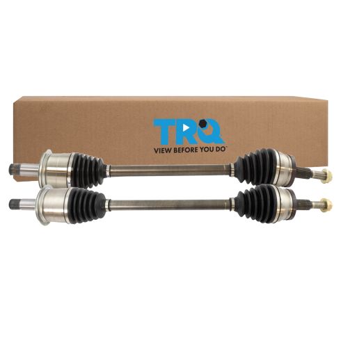
Dodge Charger Magnum Chrysler 300 Rear Driver & Passenger Side 2 Piece CV Axle Assembly Set TRQ CSA72953
Part Details:
- 2 Piece
- (1) Rear Passenger Side CV Axle Assembly
- (1) Rear Driver Side CV Axle Assembly
How to Replace Front Driver Side CV Axle 2011-15 Chevy Cruze
This video shows you how to install a driver side CV axle on your 2011-15 Chevy Cruze.
