How to Replace Head Gaskets on a 350 5-7l Small Block Chevy Engine
Created on: 2017-03-24
Watch this video to learn how to fix the top end of your Chevy 350 engine. The experts at 1A Auto will show you how to replace the cylinder head gasket on the 5.7 liter Chevy small block.
-
step 1 :Removing the Exhaust Manifold Head Bolts
- Warm the engine up to operating temperature
- Use a 14mm socket and ratchet to remove the driver side exhaust bolts and heat shields
- Keep track of the bolts position
- Disconnect the exhaust manifold from the cylinder head
-
step 2 :Disconnecting the Battery
- Disconnect the negative terminal with a 5/16 or 8mm wrench
- Move the terminal to the side
-
step 3 :Removing the Air Intake
- Loosen the throttle body thumbscrew by hand
- Label the hoses with painter's tape and a marker
- Disconnect the breather hose from the throttle body
- Disconnect the mass airflow sensor
- Disconnect the intake air temperature sensor
- Unclip the air box tabs
- Lift off the air box cover
- Pull the air intake up and out
- Remove the bottom of the air box
-
step 4 :Removing the Exhaust Manifold Head Bolts
- Warm the engine up to operating temperature
- Use a 14mm socket and ratchet to remove the passenger side exhaust bolts and heat shields
- Keep track of the bolts position
- Disconnect the exhaust manifold from the cylinder head
-
step 5 :Removing the Upper Fan Shroud
- Disconnect the positive side of the battery
- Pull the harness out of the fan shroud
- Remove the three 10mm bolts along the top of the fan shroud
- Remove the two 10mm bolts on each side of the fan shroud
- Remove the upper fan shroud
-
step 6 :Removing the Serpentine Belt
- Familiarize yourself with the route of the serpentine belt
- Insert the 3/8 inch drive ratchet into the tensioner
- Turn the tensioner clockwise to loosen the belt
- Pull the belt off the alternator
- Release the tensioner
- Pull the belt off by hand
-
step 7 :Removing the Upper Radiator Hose
- Push down and remove the radiator cap
- Have a drain pan ready
- Unscrew the drain plug
- Close the hose clamp and disconnect the upper radiator hose
- Remove the hose from the radiator
- Remove the hose from the thermostat side
- Remove the upper radiator hose
-
step 8 :Removing the Throttle Cables and AC Compressor
- Flip out the throttle lever out
- Pop the plastic rod out of its clip on the throttle cable
- Pull the cable around until it sits into the notch
- Slide the cable end out
- Collapse the tabs on the throttle cable retainers with a pair of pliers
- Push down on the tabs on the throttle cable bracket
- Pop the retainer out for the cruise control cable
- Pop the clamp from the main throttle cable
- Lay the cables out of the way
- Remove the connector on the back of the AC compressor
- Use a flat blade screwdriver to pop the container open
- Disconnect the switch on the back
- Pry out and disconnect the A/C pressure clutch connector
- Pop out the AC compressor line from its retainer
- Remove the four 13mm bolts on the top of the AC compressor
- Lift the AC compressor off of its bracket and place it on the passenger side of the engine bay
-
step 9 :Removing the Alternator
- Remove the 10mm bolt at the rear of the alternator
- Remove the two 13mm bolts at the bottom of the alternator
- Wiggle and lift the alternator out of its brackets with a pry bar
- Disconnect the wiring harness from the alternator
- Lift the rubber boot
- Remove the 13mm bolt
- Remove the alternator
-
step 10 :Removing the Tensioner
- Remove the 10mm bolt above the idler pulley
- Move the outlet hose out of the way
- Place the 10mm back in its position
- Remove the 13mm bolt from the tensioner
- Remove the tensioner
-
step 11 :Removing the Alternator Bracket
- Pry out the retainer for the power wire
- Release the radiator hose from the retainers
- Remove the two 15mm bolts from the alternator bracket
- Remove the alternator bracket
-
step 12 :Disconnecting the Wiring Harnesses
- Pinch the tabs and remove the heater hose
- Remove the clamp on the water pump to heater hose
- Remove the hard pipe
- Remove the 15mm nut securing the grounds to the thermostat housing
- Disconnect the coolant temp sensor
- Disconnect the EGR
- Pry out the retainer for the harness
- Disconnect the throttle position sensor
- Disconnect the idle air control connector
- Disconnect the crank position sensor underneath the vehicle behind the harmonic balancer
- Loosen the 14mm nut behind the bottom water pump hose
- Remove the ground
- Pop the hose out of the retainer
- Disconnect the vacuum solenoid connector
- Disconnect the MAP sensor connector
- Lift up and disconnect the white safety tab
- Pry out the ears and disconnect the from the top of the manifold
- Open the harness retainer on the passenger side valve cover and the driver side
- Disconnect the connector on the driver cylinder head
-
step 13 :Removing the Distributor Cap
- Pull the spark plug wires off the spark plugs
- Unclip the wiring retainers with a flat blade screwdriver
- Disconnect the spark plug wire from the ignition coil
- Remove the two T20 Torx screws from the distributor
- Lift the distributor cap up and out
-
step 14 :Setting the Engine Timing
- Make sure the engine is at top dead center compression
- Attach a 16mm socket and ratchet to the crankshaft pulley bolt
- Turn the crankshaft clockwise until the notch lines up with the notch on the timing cover
- Make sure both lifters for cylinder one are down
-
step 15 :Removing the Distributor
- Loosen the 13mm bolt from the distributor hold-down plate
- Remove the hold-down plate from the distributor
- Disconnect the distributor electrical connector
- Pull the distributor up and out
-
step 16 :Removing the Ignition Coil Module
- Remove the cap on Schrader valve on the fuel rail
- Place paper towels around it
- Press the top pin with a flat blade screwdriver
- Using a pair of pliers, compress the clip on the vacuum hose for the brake booster
- Remove it from the bracket
- Lay it off the side
- With a 16mm flare nut wrench, loosen the fuel fittings behind the intake on the driver side
- Remove the two 10mm nuts securing the ignition coil module bracket from the top of the engine
- Lift up on the bracket and move it around the module
- Lay the harnesses up toward the back of the engine
- Remove the two 10mm nuts on the studs below the two just removed
- Remove the ignition coil and module
-
step 17 :Removing the Spark Plugs
- Remove the 10mm bolt from the dipstick tube bracket
- Remove the eight spark plugs with a 5/8" socket and ratchet extension
-
step 18 :Removing the EGR Tube Bolts
- Loosen the 22mm EGR tube nut going into the intake
- Pop the connector out of its retainer
- Disconnect the intake breather hose on the driver side valve cover
- Remove the 13mm hold down on the EGR tube
-
step 19 :Removing the Power Steering Pump Pulley and Bracket
- Remove the 14mm nut and two 14mm bolts on the power steering pump bracket
- Install the shaft of the puller into the center of the power steering pump pulley
- Clamp the clamps around the pulley and pulley
- Place the sleeve over them
- Turn the center bolt until it locks into place
- Drive the shaft in with a 17mm and 22mm wrench
- Remove the power steering pump pulley
- Remove the remaining bolts from the power steering pump bracket
- Remove the 14mm bolt from the power steering pump bracket
- Release the hose clamp from the top
- Remove the power steering pump bracket
-
step 20 :Removing the Intake Manifold
- Remove the eight 13mm bolts around the perimeter of the lower intake manifold
- Collapse the thermostat hose clamp
- Disconnect the thermostat hose
- Remove the four 10mm bolts on each valve cover
- Lift the valve cover up and off
- Remove the vacuum hose
- Lift the intake manifold up and off
-
step 21 :Removing the Rocker Arms and Pushrods
- Remove the 16mm nuts securing the rocker arms to the head
- Familiarize yourself with the location of the parts
- Bank one and odds are on the driver side
- Bank two and evens are on the passenger side
- In order from the front
- Exhaust, intake, intake, exhaust, exhaust, intake, intake, exhaust
- Remove the rocker arm and pushrod and keep track of its original location
-
step 22 :Removing the Cylinder Heads
- Remove the 17 head bolts from the driver side cylinder head
- There are four in the top row
- There are five in the center row
- There are eight along the bottom
- Remove these with a 13mm socket, ratchet, and socket extension
- Mark and keep a location of these Bank 1 bolts
- Have a drain pan ready
- Double check for any connections
- Remove the cylinder head
- Remove the head gasket
- Remove the ground strap and the 14mm nut on the back of the passenger side cylinder head
- Repeat the process for Bank 2
- Line any motor oil in the engine to keep it from rusting
- Cover any open engine components
-
step 23 :Cleaning the Engine Heads
- Remove the coolant temp sensor with a 19mm socket and ratchet
- Soak the bracketry with cleaner or oil and grease remover
- Remove the bracketry on the sides of the both heads with a 10mm socket
- Clean the engine heads with a wire brush
- Lay the engine head on its side
- Clean the carbon out of the ports with a wire brush
- Spray out the ports with solvent
- Spray out the ports with compressed air
- Repeat this process for the other engine head
-
step 24 :Painting the Engine Heads
- Cover the ports and top of the engine heads with painter's tape
- Find a well-ventilated and warm area
- Paint the engine with Chevy Orange Engine Enamel Paint
-
step 25 :Cleaning the Engine Surface
- Blow any fluids and residue out of the engine
- Dry off the engine with a paper towel
- Scrape off any residue from the surface with a razor
- Blow any debris that fell in the engine out with an air compressor
- Blow into the threaded holes
- Wipe down all the surfaces with brake cleaner and a rag
- Clean off the engine surface with a red scouring pad
- Wipe off the gasket surface
-
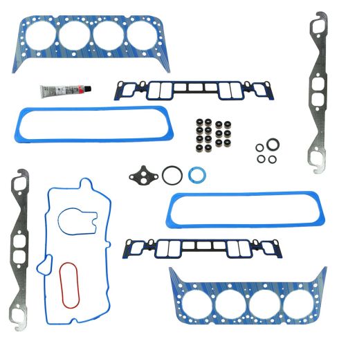
step 26 :Installing the Head Gaskets
- Lay the gasket onto the engine and align it onto the pins
- Make sure the holes are lined up correctly
-
step 27 :Installing the Cylinder Head
- Install the cylinder head onto the engine block
- Install new long head bolts into the center of the cylinder head
- Install medium head bolts into the front and back of the cylinder head
- Install the short head bolts into the side of the cylinder head
- Torque the bolts to 22 foot-pounds in the proper torque sequence
- Use a torque angle gauge to torque the long bolts to an additional 75 degrees
- Use a torque angle gauge to torque the medium bolts to an additional 65 degrees
- Use a torque angle gauge to torque the small bolts to an additional 55 degrees
- Repeat the process on the opposite side
-
step 28 :Reinstalling the Pushrods and Rocker Arms
- Clear out the grease in the engine valley
- Reinstall the pushrods and rocker arms in their correct slots without tightening
- Rotate the crankshaft until the top dead center mark is aligned on the pulley and the timing cover
- Check that both lifters are down
- Adjust the exhaust valves on cylinder 1, 3, 4, and 8
- Adjust the intake valves on 1, 2, 5, and 7
- By spinning down the nut on the rockers while rotating the push rod with your fingers
- Get rid of the lash until it's harder to rotate and has not up and down movement to it
- Rotate the nut another 160
- Rotate the crankshaft back to top dead center
- Adjust the exhaust vales on 2, 5, 6, 7
- Adjust the intake valves on 3, 4, 6, 8
- Reinstall the 14mm stud into the back of the head
- Reinstall the two ground wires onto the stud
- Tighten the 14mm nut
-
step 29 :Cleaning the Manifold and Engine
- Lay the intake manifold over
- Remove the old gasket material
- Remove the gasket sealer along the valley portion
- Scrape off the gasket sealer with a razor blade
- Wiper the gasket surface with some solvent
- Scrape any gasket from the engine
- Wipe the engine surface with some solvent
-
step 30 :Installing the Intake Manifold
- Lay the intake manifold gaskets into the locking pins
- Lay gasket maker into the valley corners and the engine
- Set the intake manifold into place
- Reinstall the seven bolts into the manifold
- Leave the EGR bolt out
- Face the manifold from the face of the car
- Tighten the bolts in the following sequence: first round to 71 inch-pounds, second to 106 inch-pounds, third to 11 foot-pounds
- Tighten the second bolt in on the passenger side
- Tighten the third bolt in on the driver side
- Tighten the third bolt in on the passenger side
- Tighten the second bolt in on the driver side
- Tighten the fourth bolt in on the passenger side
- Tighten the fourth bolt in the driver side
- Tighten the first bolt in on the passenger side
- Tighten the first bolt in on the driver side
-
step 31 :Installing the Valve Cover
- Install the valve cover gasket to the valve cover
- Lay the valve cover into place
- Tighten the four 10mm bolts
- Repeat the process for the other side
- Torque the bolts to 106 inch-pounds
- Step 20: Reattaching the Fuel Line Fittings and EGR Tube [28:35]
- Realign the EGR tube
- Tighten the 22mm bolts to the EGR tube
- Line up the bracket to the EGR tube
- Tighten the 13mm bolt to the EGR tube
- Reattach the fuel lines at the rear of the intake manifold with a 16mm flare wrench
-
step 32 :Preparing the Distributor
- Remove the two T20 Torx screws from the new distributor cap
- Separate the new cap from the new distributor
- Remove the two T10 Torx screws from the distributor rotor
- Remove the rotor from the distributor
- Line up the 8 on the on distributor with the notch on the housing
-
step 33 :Installing the Distributor
- Set the distributor into place with the flat part of the housing facing the engine
- Start the 13mm bolt into the distributor hold-down
- Install the rotor onto the distributor
- Carefully tighten the two T10 bolts for the rotor
- Connect the distributor electrical connector
-
step 34 :Reinstalling the Power Steering Pulley
- Install the ignition coil and control module
- Tighten the 10mm bolts
- Lay the hold down bracket for the wiring harness into place
- Reinstall the two 10mm nuts onto the hold down
- Reinstall the power steering and A/C bracket
- Reinstall the 13mm hardware
- Insert the power steering pulley into place
- Insert the power steering pulley puller and tighten the pulley into place
-
step 35 :Reinstalling the Alternator and Harnesses
- Press the clamp for the water pump hose and slide the hose into place
- Reinstall the alternator bracket
- Tighten the 14mm hardware with a socket and ratchet
- Press the alternator into place
- Tighten the 13mm bolts to the alternator
- Tighten the 10mm bolt to the alternator
- Connect the connector on the driver cylinder head
- Connect the harness retainer on the passenger side valve cover and the driver side
- Connect the from the top of the manifold
- Connect the white safety tab
- Connect the MAP sensor connector
- Connect the vacuum solenoid connector
- Clip the hose into of the retainer
- Connect the ground
- Tighten 14mm nut behind the bottom water pump hose
- Connect the crank position sensor underneath the vehicle behind the harmonic balancer
- Connect the idle air control connector
- Connect the throttle position sensor
- Clip in the retainer for the harness
- Connect the EGR
- Connect the coolant temp sensor
- Connect the 15mm nut securing the grounds to the thermostat housing
- Insert the hard pipe
- Insert the clamp on the water pump to heater hose
- Pinch the tabs and connect the heater hose
- To the alternator, reinstall the power terminal, lock washer, and 13mm nut
- Close the boot over the nut
- Connect the wiring harness
-
step 36 :Reinstall the Throttle Cables and the AC Compressor
- Connect the throttle cables into the clips
- Open the throttle body blade
- Loop the throttle cable into the square slot
- Send the round cruise control cable into its slot and snap it over its tab
- Install the vacuum booster line on the rear of the intake manifold
- Place the AC compressor into its bracket
- Reinstall the four 13mm bolts into the compressor
- Reconnect the connector on the A/C compressor clutch
-
step 37 :Installing the Serpentine Belt
- Reinstall the tensioner and its 13mm bolt
- Loop the belt around the crank pulley
- Bring it around the water pump
- Bring it under the power steering pulley
- Bring it around the A/C Pulley
- Bring it around the belt tensioner
- Bring it under the idler pulley
- Pull the tensioner clockwise with the 3/8 inch ratchet
- Pull the belt over the alternator
- Release the tensioner
-
step 38 :Installing the Upper Radiator Hose
- Insert the upper radiator hose into place
- Compress the clamps and connect it on the thermostat and radiator side
- Reinstall the upper fan shroud
- Tighten the seven 10mm bolts to the fan shroud
- Clip in the power wire
-
step 39 :Tightening the Exhaust Manifold Bolts
- Tighten the 10mm bolt to the side of the head
- Install the exhaust manifold gasket
- Tighten the 14mm bolts and heat shields by hand
- Tighten the bolts to the exhaust manifold
- Repeat the step for the opposite side
-
step 40 :Installing New Spark Plugs
- Insert the spark plugs with a spark plug socket
- Tighten the spark plugs with a socket and ratchet
- Repeat this step on the remaining seven cylinder
-
step 41 :Installing the Ignition Coil
- Place the coil plug onto the ignition coil
- Place the passenger rear on the distributer marked C
- Connect the spark plugs as 6, 4, 2, 8 on the passenger side
- Connect them to the corresponding spark plug
- Drive side is 1, 3, 5, 7
- Route the spark plug wires along their appropriate rungs
-
step 42 :Installing the Upper Air Intake
- Install the lower half of the airbox
- Press the upper intake into place
- Tighten the thumb screw
- Connect the PCV breather hose
- Reinstall the MAF sensor
- Reinstall the air intake sensor
- Reinstall the air box lip
-
step 43 :Reconnecting the Battery
- Connect the negative terminal with a 5/16 or 8mm wrench
- Connect the positive terminal with a 5/16 or 8mm wrench
-
step 44 :Starting the Vehicle
- Refill the oil
- Refill the coolant
- Start the vehicle
Tools needed
-
Razor Blade / Gasket Scraper
Torque Wrench
Rust Penetrant
Channel-Lock Pliers
Pry Bar
Complete Metric Wrench Set
Brake Parts Cleaner
Safety Glasses
Gloves
Flat Blade Screwdriver
T20 Driver
Paper Towels
Bungee Cord
Anti-Seize Grease
Wire Ties
Painter's Tape
Drain Pan
Wire Brush
Flashlight
Needle nose pliers
Marker / Writing Utensil
Complete Metric Socket Set
Hi, I'm Mike from 1AAuto. We've been selling auto parts for over 30 years! We're dedicated to delivering quality auto parts, expert customer service, and fast and free shipping, all backed by our 100% satisfaction guarantee. So visit us at 1AAuto.com, your trusted source for quality auto parts.
In this video to celebrate us hitting 400,000 subscribers, we're going to be tearing off the top end of the engine in our 1996 GMC Sierra K 1500. Now, this is the super popular 5.7L GM V8. These motors came in tons of vehicles. They're popular in tons of swaps, and we're going to pull the heads off to do the head gaskets and show you guys a lot of the intricate inner workings of engines.
If you like this video, please click subscribe. We have a ton more information on this truck as well as many other makes and models. You'll also get to check out the time-lapse video that we're going to be making of this at the same time. If you ever need parts of your vehicle, be sure to check out the link down in the description over to 1AAuto.com. Thanks again for subscribing and enjoy!
The step we're going to take here is to back our truck up to the garage. Warm the engine up to operating temperature. Pull it back in, and get the exhaust manifolds off while they're still hot.
Now, granted it's not a lot of fun working around a hot exhaust manifold, but it's even less fun to break the bolts off on your exhaust manifold. Even though we're taking the heads out and we could change the studs and bolts out a little bit easier on the bench than you can in the vehicle if you can avoid this step, it's going to save you a lot of time and hassle later in the project.
Now, careful because the exhaust manifolds are hot. Use a 14mm socket and ratchet to remove the exhaust bolts; there are six on either side. When doing a big job like this, it's very important to keep all your hardware organized because you're going to have a lot of it. What I did is I made a little drawing of our exhaust manifold. Mark them driver and passenger, and punch some holes in so I can remove all the bolts. Put them in here. Set this aside and know what these bolts are and where they go when the engine goes back together. We have some heat shields that are going to come off as well; be sure to keep track of these. Our exhaust manifolds are now disconnected from the cylinder heads. We don't need to remove them completely for our purposes though.
Remove the negative post from your battery using a 5/16 or an 8mm wrench. Be very careful; this wrench isn't long enough, but if you have a longer one, you may be able to hit the positive battery terminal with it. You want to be very careful you don't do that. Remove the terminal and isolate it from the battery. That will give us a little more access to the other side.
We'll undo the thumbscrew on top of the throttle body. Pop that off, disconnect the breather hose, undo the mass airflow and intake air temp sensors, and where we're going to be disconnecting so many wires here. I went ahead and labeled all of them with painter's tape. You can choose to do that or take pictures. There's a variety of ways to do it.
Undo the latches on the air box. Lift it up. Remove your filter take, and take the entire intake setup off the truck. Wiggle the bottom of the air box off and remove all of that so we have access to our exhaust manifold. We'll now repeat the process removing the same six bolts on this side.
You'll need to disconnect the positive side of the battery. We removed it entirely so we had some more room to show you guys what was going on. Pull the harness coming from the battery and over to the ECU out of the top of the fan shroud. Just move it off to the side for now. We'll then remove the three 10mm bolts along the top of the fan shroud. We'll then use a 10mm socket ratchet and a long extension to get it looks like there were two 10mm bolts on each side. However, we've only got one so remove one from the each side of our fan shroud. You can then remove the upper radiator shroud from the vehicle.
Use a 3/8 breaker bar or ratchet to release the tension from the tensioner and remove your serpentine belt.
Remove your radiator cap by pushing down and turning it counterclockwise. If you look down below your upper radiator hose, you'll see the drain plug for the radiator. We're going to reach down there and we have our drip pan underneath the truck. We're going to reach down and unscrew that. Using a pair of pliers or groove jaws like we have here, collapse the clamps on the upper radiator hose then remove the hose from the radiator. We'll then do the same thing on the thermostat housing side of the hose. You can now remove the upper radiator hose from the vehicle.
Remove the throttle cables by flipping the lever out. Pop the plastic one out of its clip, and then pull the cable for the main throttle cable around until it sits into the notch. You slide the cable and out. Use a pair of pliers to collapse the tabs on the throttle cable retainers, and pull them through their bracket. Push down on the tabs on the bottom side of the throttle cable bracket. Pop the retainer out for the cruise control cable. Then use your flat blade screwdriver to pop the clamp open for the main throttle cable, and lay both of these out of the way. Remove the connector on the back of the A/C compressor. Use a flat blade screwdriver to pop the retainer open, then lay it over the compressor. We'll also disconnect the switch on the back. We'll use a small flat blade to pry off the ears on the A/C compressor clutch connector, just let all that hang out of the way for now. Pop out the A/C compressor line on the passenger side of the engine, pushing the tabs down and pulling it out of the retainer. Then remove the four 13mm bolts on the top of the A/C compressor. We'll then lift the A/C compressor off its bracket and carefully place it in the passenger side of the engine bay.
Remove the 10mm bolt on the back of the alternator. We'll then remove the two 13mm on the front. Pry the alternator up and out of its housing and remove the connector. Pull back the boot and remove the 13mm nut on the power stud. Remove the alternator from the vehicle.
Remove the 10mm bolt right above the idler pulley. This secures the outlet hose on the water pump to this accessory bracket, which we're going to remove. Just so we don't lose this bolt, we'll move the hose out of the way. You can release it from the retainer if you have to, and just throw that 10mm back in there a couple of threads so we don't lose it. Use the 13mm socket and ratchet to remove the center bolt from the tensioner. Remove the tensioner from the vehicle.
Pry open the retainer for the alternator power wire. Pull that out of the way. We'll then use our screwdriver to release this radiator hose as well. This is the one for the heater cord that goes to the top of the intake manifold. Remove the two 15mm bolts, as well as the 15mm nut securing the alternator bracket to the front of the engine. We'll do this with a 15mm socket ratchet and extension. Remove the accessory bracket from the vehicle. Pinch together the two plastic tabs on the heater hose, wiggle them out of their holder. Lay that hose off to the side. Remove the clamp on the water pump to heater hose. Remove the hard pipe way. Lay that off to the side as well.
Remove the 15mm nut, securing the grounds to the top of the thermostat housing. Remove the grounds. Put that nut back on finger tight just we don't lose it later. We'll then lift up on the tab and disconnect the cooling temp sensor and the EGR. Pry out the retainer for the harness. We'll then disconnect the throttle position sensor, as well as the idle air control valve connector. We'll let that whole harness hang out of the way.
Underneath the vehicle, you'll find the crank position sensor behind the harmonic balancer; disconnect that. Move the harness up and out of the way. Use a 14mm wrench to loosen this nut behind the bottom water pump hose for the lower radiator. There's a ground strap on here that we'll need to remove in order to get this harness up and out of our way. Slide the ground off of the stud then we'll just throw that nut on their a couple of threads to hold it in place then have retainer right here that we'll need to pop open with our flat blade screwdriver; another retainer here. Disconnect vacuum solenoid connection here as well as the one behind it. It's a little tricky to see under the harness, but you'll also need to remove your map sensor connector and release this section of the harness. Lift up on the white safety tab and use a small flat blade screwdriver to pry out the ears. Carefully lift up on the connector and remove it from the top of the manifold.
Open up the harness retainer on the passenger side valve cover. If we have enough stuff disconnected here, we also have one over here on the driver side. You also have to disconnect the connector over on the driver cylinder head here. We should have enough slack to lay our harness to the back of the engine. We're not ready to do just yet.
Remove the spark plug wires from the spark plugs. Don't worry about where these go right now, because the distributor is marked with the positions of all the plug wires showing. We'll show you the firing order when be put it back together. Be sure to open up all the wire looms and release the plug wires from them. We'll repeat these steps on the opposite side. Disconnect the plug wire from the ignition coil as well.
Remove the two T20 Torx screws one here and one on the backside of the distributor. We'll do this using a T20 Torx bit, a ratchet, and an extension. These are not captured, so what I like to do is loosen them up pretty much all the way and then lift up on the distributor cap and bring that out nice and smooth and level so we're careful not to lose those screws. Before moving your distributor, be sure that the engine is at top dead center compression.
This means that the vehicle's distributor will be in the correct timing placement, so when we align the timing marks and reinstall it later. It will go and hassle-free. This is a very important part of the engine's timing, which will allow us to set our distributor in the correct place. It's a good time to show you what TDC is and why we use it. On the driver side of the timing cover, there's this little ear with a notch on it. We use a 16mm socket and ratchet on the center bolt of the crank pulley to rotate it, and this is a bit more difficult with the engine assembled because you'll have compression you need to deal with.
Rotate it clockwise only nice and smooth and slow and you'll see a notch on the crank pulley. This notch, you overshoot it, you have to keep going clockwise. You can't rotate these backwards. Right there, tells us that our piston is at top dead center. This means that the number one piston is at its highest point in the cylinder bore and you can see that this is actually almost flush with the deck of the block at this point. The other important part is that we're going to want that on top dead center compression.
Now, if the engine was together right in those last few degrees before I got that line marked up with a crank, it would get really tight because of the compression in the motor. If you don't feel that compression when rotating it, it means cylinder number one is in its intake stroke which is not what we're after for timing. However, where there is no compression due to the head being off right now, another easy way to check is both our lifters are down can see what one looks like when it's up here. These are what open the valves. These are part of what open the valves in the vehicle. If they're both down, both our valves are closed.
Our piston would be at the top of the bore, and our engine would be in its compression stroke on cylinder number one. Using a 13mm wrench, loosen the bolt on the distributor hold down plate, which is below the distributor on the passenger side of the motor. They do make special distributor wrenches for this, which are nice to have, but you can get by with a regular wrench. It's just a little more time-consuming. Remove the hold down bracket from the distributor. Disconnect the electrical connector on the back of your distributor and carefully wiggle the assembly up and out at the back of the engine.
Remove the cap on the Schrader valve on your fuel rail. We'll then put some paper towels around it, and use a flat blade screwdriver to press the top pin. Be sure to wear safety glasses and stay out of the way of this, because they tend to bleed off a little bit of pressure. Using a pair of pliers, compress the clip on the vacuum hose for the brake booster and remove it from the bracket. It helps to twist this to free them up. Pull it out, and lay it off to the side. Using a 16mm flare nut wrench, loosen the fuel fittings on the back of fuel lines. These are down behind the intake on the driver side. Move the two 10mm nuts securing the ignition coil and control module bracket to the top of the engine. We'll do this using a 10mm socket ratchet and extension. Lift up on the bracket and move it around the module and the coil. Be careful of any other sensors in the area. Now, lay the whole engine harness up on the back of the engine, which is going to make this whole process a lot easier for us. We'll now remove the two 10mm nuts on the studs just below the two we just removed. You can then remove the ignition coil and module as well as the bracket from the engine.
Remove the 10mm bolt securing the dipstick tube bracket to the side of the cylinder head with the 10mm socket and ratchet. Rotate it out of the way. Using a 5/8 spark plug socket, ratchet, and socket extension. Remove the four spark plugs from each cylinder head, so there are eight in total. Repeat this process with the remaining three spark plugs on this side, and then all these steps on the opposite side. Using a 22mm wrench, loosen the EGR tube nut going into the intake at the driver side front of the lower intake manifold. Pop the connector out of its retainer. Lay that off to the side.
Disconnect the breather hose on the intake coming from the driver side valve cover, and lay it out off to the side. Using a 13mm socket, ratchet, and extension, remove the hold down on the EGR tube at the back driver side of the intake manifold. Remove the 14mm nut and two 14mm bolts and the power steering pump bracket. We'll do this with a 14mm socket and ratchet.
To remove the power steering pump pulley, you'll need a power steering pump pulley puller tool, which we have here. It's actually few separate pieces. We'll show you how they go together and how to remove the pulley with them. The fan on his truck is staggered, so the blades are not equidistant from each other. The largest gap is here, so we'll rotate that in front of our power steering pump pulley so that it doesn't interfere. Install the shaft of the puller into the hole in the center of the power steering pump pulley. Get that down as far as you can and then loosen the nut here. Make sure that it's still on the threads, even when it's bottomed out. We'll then take these two half-moon style clamps, and place the wider end around the pulley with the skinnier end around our puller. This sleeve will go over them and hold them together.
You can now turn the center. It will hold the nut or vice versa and so that locks into place. We use a 21mm wrench to hold the nut and a 17mm to drive the shaft in which will pull the nut with our clamp and sleeve on it out, bringing the pulley off of the shaft. Ours is really pressed on there tight, so we're using a ratchet and a socket just to get a little more leverage on it. It will eventually pop off, and we can remove all of this from our vehicle. Using a 13mm socket and ratchet, remove the remaining bolts from the power steering pump bracket. Ours was covered in some grease, so we didn't see it at first, but at the bottom inside corner of the power steering pump bracket, there is a 14mm bolt that will need to be removed; remove the bolt. Release this hose clamp at the top with a flat blade screwdriver.
Remove the power steering pump bracket. Remove the eight bolts around the perimeter of the lower intake manifold; there are two in each corner with a 13 mm socket and ratchet and an extension is necessary. Using a pair of pliers, collapse the clamp on the thermostat hose going into the water pump; you can do this on either end. It's just that our other one looks pretty rusty so we're to leave that along for now. Slide the clamp off, wiggle the hose to free it up, and then pop it off. Remove the four 10mm bolts on each valve cover with the 10mm socket, ratchet, and extension. Remove the valve cover.
Be sure to mark which is left in, which is right as they are different. Repeat these steps on the opposite side. Remove this valve cover as well. Don't forget to remove the vacuum hose before removing your intake manifold. Once the valve covers are off, you can lift up and remove your intake manifold. Remove all of the 16mm nuts, securing the rocker arms to the head. You'll need to keep the rockers and pushrods organized so they go back where they came from. We'll just remove all the nuts for now, and then we'll show you how to keep them in line.
To keep things organized, they do make specialty boards designed to keep all of these small block Chevy parts in line. I've simply numbered each cylinder. This is how the V of our engine works. Bank one is on the driver side. Bank two is on the passenger, and then it's odds and evens from there. It starts exhaust, intake, intake, exhaust, exhaust, intake, intake, exhaust on each side, so what we'll do is here we have our number two exhaust rocker arm and pushrod. We'll pull the pushrod out. We'll pull the pushrod out, put it next to our exhaust. Put a rocker arm on there and our washer and nut so they go back exactly where they came from, and we'll repeat this process for all the remaining rocker arms, pushrods, nuts, and washers on each side of the engine.
Remove the 17 head bolts from the driver's side cylinder head. There are four in the top row, five in the center row, and eight along the bottom. We'll remove all of these with a 13mm socket, ratchet, and extension. Much like we've done with every other part that comes off the vehicle, I've made a board to mark the locations of our bolts. Be sure there's a drain bucket underneath the vehicle, and double check that there are no more connections attaching your cylinder head to any other part of the vehicle before lifting it off and removing it. Be careful as these do have some way to them.
Remove your head gasket. Remove the ground strap and nut on the back of the passenger side cylinder head. Do this with a 14mm wrench. Once you get that off, you can repeat all these steps from the driver side over here. Be sure to move your drain bucket before you finish removing the bolts on the opposite cylinder head.
Remove the coolant temp sensor with a 19mm socket and ratchet, and, if you'd like, you can also remove all of the bracket tree on the sides of the head with a 10mm socket, ratchet, and extension. Be sure to mark or take pictures so these brackets go back in the exact same place they came from. Now, I've been soaking these heads in a mineral spirit cleaning solution in our parts washer to loosen up all of the dirt and debris. If you don't have access to one or those cleaners, you can use a variety of different oil and grease removers like a brake parts cleaner or Carb Clean. There's also a number of different engine degreasing solutions as well as some home remedies that people make or mix themselves. All of these are acceptable solutions.
All we want to do is get a wire brush and just start getting all the junk off of the heads. What we're going to do now is use a small wire brush to clean all the carbon out of the ports, or as much of it as we can. Just because we have it off and it's something we can do to help our engine breathe a little easier run a little better, we're going to brush it and then blow it out with compressed air, but I'm actually going to lay it on its side here while I'm cleaning it out to try to prevent everything from falling down on top of the valve even though we will have the valves out later and we can blow it out then.
Any debris, I don't have to get into the cylinder head. I don't want to get in there, so I'll lay it on its side and clean it out that way. After some scrubbing, spray it out with some solvent. I'm using a brake cleaner, but there's a variety of solutions you can use. Then reach in there with a paper towel, and wipe it out. If you have compressed air, I recommend you blow it out as well. Look at all that dirt and debris that comes out of the engine. This is all unburnt fuel and oils, and other chemicals that go inside of the combustion chamber, and all that's going to do is clog up our ports and prevent our vehicle from producing power and being efficient.
We'll give you a little side-by-side and that was just a quick cleaning. You can really get in there and scrub those out, but look at the difference between just a few seconds of scrubbing and wiping out that port versus all the other ports. This is going to flow better breathe better. We're going to get a more efficient, more powerful engine. Just go through and clean out all of your ports intake and exhaust the same way we did with the first one. Be sure to keep those brushes clean. We're just using some brake cleaner or whatever solvent you're using to clean the engine, just spraying out all that grease and goo; grabbed a bucket to keep it in. The cleaner you keep that brush, the faster and easier you're going to be able to remove all this carbon buildup.
Lay of our heads make the exhaust ports face down when we have it laying flat, so I just grabbed a block of wood, and I'm going to put under the head to keep them at least flat and hopefully help drain out any material we removed. Then we'll clean these the same way we did on our intake side. This isn't even everything, but this is just some of the fun off and debris from a paper towel I placed under our ports just to give you an idea of how much junk really gets in there.
Now, you don't absolutely need to clean this as part of the job. For the amount of time we just spent doing it, our engine will thank us. The difference between our dirty cylinder head on your left and a clean cylinder head on the right is pretty clear. Not only are we going to keep dirt and debris from falling in the engine ports and gasket surfaces when we reassemble, but also we've opened up the holes through which our motor breaths, which is going to make everything run and work a lot smoother. We've masked off our tool cart.
Our engine has already been cleaned and degreased, and now we're going to spray it with some Chevy orange engine enamel paint. This paint is designed for the high temperatures created when an engine is running. Be sure to wear proper safety equipment and only do this in a well-ventilated and warm area. Now, allow about 10 to 15 minutes between coats before laying another, and we're probably going to do two or three coats on this to get it looking nice. This may require more or less depending on the condition of the steel and the type of paint you use. For the last coat of paint, we're going to go on a little thicker and let it sit a lot longer. Again, this is a cylinder head. Don't be worried about imperfections in the paint, runs, fish eyes. The fact that you can see the texture of the rusted head underneath, it's really just to pretty it up a little bit. It's not like you're painting a body panel. You can put the last coat on nice and thick to make sure we cover up any of the white spots. Now, we'll let this side sit until the paint is dry.
Now in our shop, we only work on one vehicle at a time, but if you're in a place where you have more than one project going on at once, want to keep any open engine components like the head were here, we have the block covered with a trash bag or some kind of other wrap to keep dirt and debris from getting into the engine. All the surfaces are very fine machine, and any dirt and debris that gets in there and stays in there when the engine runs could cause some serious damage. We'll uncover it now that we're to work on it, and, just to be sure, we'll take some compressed air and blow everything out of the cylinders like fluids and residue that fell in there when we removed our heads.
Now the majority of what you're seeing coming out of these cylinders right now is some motor oil that I actually put in there to keep the exposed cylinders from rusting and also to help create a barrier for anything trying to sneak past the rings on the pistons. Now, we'll go in there and just wipe out all that moisture with a paper towel. You want to check before you go wipe the cylinders out there are no large particles anywhere that you're going to rub into the cylinder more while wiping it out. If there are, just reach in there and pick them out. We'll take a razor blade scratch off all those surfaces. Once again, this stuff is going to fall into the cylinders a little bit, so we'll have to blow them out one more time, but by getting all that moisture and everything out of there on the first run, that'll keep it from wadding up and getting stuck so scrape it down.
Again, you don't want to use any kind of heavy abrasive or power tools to clean these off because this is a machine flat surface, and you don't want to risk changing any of the surfaces. We'll do the same thing on the opposite side. Now, we'll blow all of the debris back out of the engine. You'll also want to make sure you blow into each one of the threaded holes for the head studs, and get any debris or fluids out of there. We'll then wipe down all the surfaces with brake cleaner and a clean paper towel or rag. Once the surface is wiped down, be sure to get inside of the cylinders again as well.
Once the bulk of the material was been removed from the gasket surfaces, go ahead and get the fine stuff with some red scouring pad. We'll repeat this step on the opposite side. You want to make sure that the block as well as the gasket surfaces on the bottom of the head look this clean. We will have to blow out the cylinders again, and give it one more wipe with some brake parts cleaner, but we'll want to make sure that this is the finish of both mating surfaces. Now, it's time to put our heads back on. We'll give our gasket surface one last wipe with some brake clean and a clean rag or paper towel. Be very careful not to let any debris fall into the engine otherwise you'll be doing the blowing out process again which tends to make a mess of fluids and requires you to wipe it down again so just go easy. You don't need a lot of pressure here. We've already got this nice and shiny and clean. We're just trying to remove any oil or residue that's left on it.
There's no left and right to the head gaskets. However, you do need to pay attention to the label saying this side up. Place it in and align it onto its dowel pins and just take a second to double check that all the holes line up correctly. This is not something that you want to use any type of sealant on. With the gasket on its dowel pins, you can now reinstall the cylinder head onto this side of block. Reinstall your cylinder head onto the block, being very careful not to damage or misaligned the gasket in the process. It will rest on to the dowel pins just like you gasket did. You can now install a few of the head bolts.
You always want to use new head bolts whenever you take the head off. I'm installing two of the longer ones now just to keep it in place. The two medium length bolts will go in the center row of the head, one at the front-most hole in the center and one in the rear-most. Your short bolts will go on the outside of the head, all the way along the bottom. The rest of the top and middle row will be filled in with the longest bolts. Be sure not to use any lubricants when installing these, as your new head bolts should come coated in a thread sealant to prevent coolant from leaking through them once the engine is running.
Now, as with any hardware, these bolts are a half-inch even the ones removed were 12mm. All I'm going to do is use my half-inch socket and ratchet, and I'm just tightening from the wrist here just to snug this down. I've not been put anything torque or force on them other than to just get them down and touching the head to make the torqueing process go more smoothly. You want to stagger this and work from the inside out. You don't necessarily need to follow the torque sequence exactly here, but I'm going to follow the same path you would with the torque sequence anyway just as a precaution. Torque all of the bolts to 22-foot-pounds on the first pass in proper torque sequence. We'll now use a torque angle gauge to torque all of our long bolts, an additional 75 degrees. The two medium bolts, an additional 65; and the short bolts on the bottom, an additional 55 degrees. The way this works is we'll install it onto the bolt, rotate the center section to zero it, and then add the appropriate number of degrees.
Sometimes it's helpful if you left your exhaust manifolds on the truck like we did, because the studs on the other end are so rusted, so get a bungee cord and secure the manifold up and out of your way. Then we'll repeat the process of installing the head on the opposite side. Just because we were blowing around a lot of the dirt and debris from our engine, I can see that there's a lot of debris that made its way into the engine valley around the lifters. This is true of your motor too. Just take paper towel and wipe that stuff out.
You can now reinstall all of your pushrods and rocker arms. Start by installing the pushrod into the lifter. Reinstall your pushrods, and set the rocker on with the washer. Place it in, and the beveled acorn side of the nut actually faces up on this. We'll just start this by hand, because we're going to need to make an adjustment to all 16 valves, so just repeat this process and install all of your rocker arms and pushrods into their original locations.
Using a 16mm socket and ratchet, rotate the crankshaft until the top dead center mark is aligned on both the pulley and the timing cover; that's too far. You overshoot it, you have to keep going clockwise; you can't rotate these backwards. When the timing mark is aligned, you'll want to check that both valves, in this case, where our valves are still loose, we'll be checking that both lifters are down.
If these lifters are up… Actually, it will be this lifter that is up. It means that your engine is on the exhaust stroke but ours are both down so we're at top dead center compression, and we can now adjust the exhaust valves on cylinder one, three, four, and eight in the intake valves on one, two, five, as well as seven. To do this, we'll spin down the nut on our rocker. In our case, this is a 16mm while rotating the pushrod between our fingers. You can see there's a lot of lash here. The goal is to get rid of that lash. You shall feel the pushrod gets a little harder to rotate and it has no up and down movement to it.
At this point, you'll want to rotate the nut another 360 degrees or one full turn. This sets the preload on the lifter. Now, you can use a torque angle gauge if you'd like. However, since we're just making 360 degrees, I'm going to set the handle with my wrench perpendicular to the head and just spin it around once without letting off. We'll now repeat this process on the exhaust valves for cylinders three, four, and eight, as well as the intake valves on cylinder one, two, five, and seven.
Once you've set your valves at top dead center compression, we'll use our 16mm socket and ratchet to rotate crankshaft back to top dead center, because your cam moves at half the rate. Your crankshaft does rotating the crankshaft 360 degrees rotates the camshaft 180 degrees. This means that we'll be at top dead center
Shop Products

How to Replace Lower Intake Gasket 2008-12 Ford Escape
Check out this video for instructions on how to replace lower intake gaskets on a 08-12 Ford Escape. The 1A experts have the know how to help you do it.
